


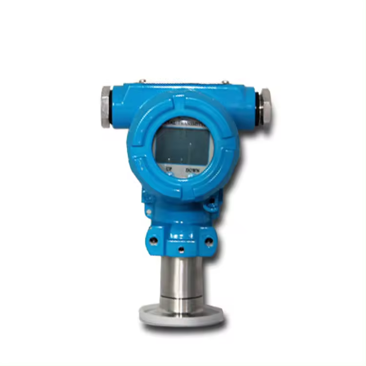

Intelligent Digital Pressure sensor with HART Communication PT-2088
PT2088 Intelligent Digital Pressure sensor is a high-precision smart instrument product developed by our company based on years of scientific research and practice.
The sensor of the smart transmitter is a high-precision and miniaturized smart sensor produced using advanced foreign technology. In terms of conversion principle, a microprocessor is used to replace the analog signal amplification circuit and A/D conversion circuit, and digital compensation technology is used to compensate for the temperature. , improve the measurement accuracy and reduce the temperature drift. It has the characteristics of good long-term stability, high reliability and strong self-diagnosis ability. With its extremely high praise, it has become a mainstream product in the transmitter market.

Intelligent Digital Pressure sensor Features:
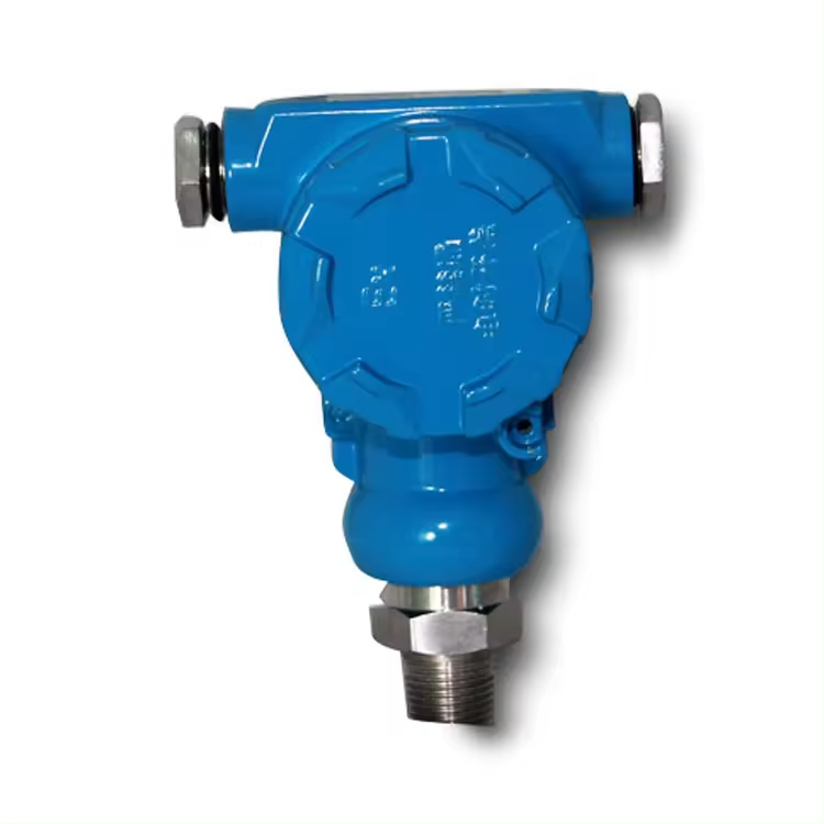
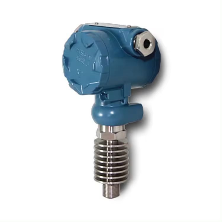
The PT2088 series intelligent transmitter is suitable for measuring the flow, liquid level and pressure (gauge pressure, differential pressure, absolute pressure) of liquid, gas and steam media. The PT2088 series can be divided into two series according to its use.
PT2088GP pressure transmitter
PT2088AP absolute pressure transmitter
While PT2088 has the characteristics of stable performance, high reliability and strong overload resistance, it also adds advanced digital compensation and communication functions. This makes the PT2088 series smart transmitter a high-precision smart transmitter with a wide range of uses. The transmitter can complete testing, configuration, calibration and other functions through our company’s HRTMASTER configuration/debugging system, and is also compatible with the ROSEMOUNT275 handheld terminal. Local zero point and span adjustments can be made from the keys in the control room or on the transmitter circuit board through a handheld communicator or debugging equipment.
When performing remote communication, please note: there must be a resistance of no less than 250Ω between the terminal block and the power supply. Before using the HRTMASTER configuration/debugging system to connect to the transmitter, please be sure to read the relevant product manual.
Features:
- Increased flexibility and enhanced functions due to the use of microprocessors;
- Has strong self-diagnosis ability;
- The measuring range covers a wide range of 0-2KPa~60MPa;
- The accuracy is better than 0.1 level, and the range ratio is better than 10:1;
- Zero point and span adjustment do not affect each other;
- Both remote and local zero point and range adjustment;
- Two-wire system, compliant with HART® protocol, can carry out digital communication with ROSEMOUNT275 without interrupting analog output;
- The sensor has non-volatile memory;
- Good stability, high accuracy, adjustable damping, and strong one-way overload resistance;
- No mechanical transmission parts, less maintenance work, strong and vibration-resistant;
- All common parts, sensors and electronic boards are interchangeable without affecting the performance of the transmitter, making maintenance more convenient;
- The diaphragm material in contact with the medium is optional, and the explosion-proof shell structure is available;
- Proven superior performance and reliability;
Precautions for installation in hazardous locations
In order to maintain the explosion-proof function of the installed transmitter, the following matters must be paid attention to (see the explosion-proof instructions for details).
1. The cover must be tightened to ensure at least 6 engagements, and the threads must not be damaged.
2. The connection between the sensor and the electrical housing must be engaged at least 6 times, and the threads must not be damaged.
3. Wiring holes must be sealed with suitable seals.
4. If the other wiring hole on the housing is not in use, it must be plugged with a threaded metal plug, engaging at least 6 buckles.
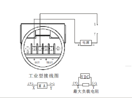
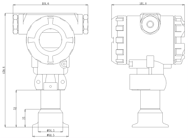
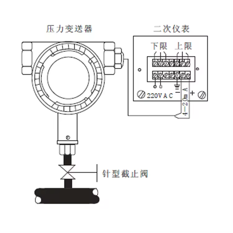
The power-signal terminals are located on the terminal block side of the electrical housing. When wiring, open the end cover on the terminal side (marked) FIELDTERMINAL. The terminal block is as shown in Figure 3-3. The left terminal is the power supply-signal terminal (marked OUT+ and OUT-), and the right terminal is the test terminal. (Test) or current indicator connection terminal (marked TEST+ and TEST-). The test terminal has the same current signal 4~20mADC as the power supply-signal terminal; it is used to connect the indicating instrument or for testing.
The power of the transmitter is supplied to the transmitter through the signal line (the signal line and the power line share two lines, that is, a two-wire system, so no additional electronic power line is required). Special attention should be paid when wiring the transmitter. The positive pole of the power supply-signal line is connected to the positive pole of the power supply-signal + terminal (marked OUT+) on the left side, and the negative pole is connected to the power supply-signal- (marked OUT-) terminal. Do not connect the power-signal wire to the test (test) end. Otherwise, the output circuit of the transmitter will be short-circuited, causing the circuit device to open circuit.
The transmitter signal wire does not need to be shielded, but two twisted pairs twisted together work best. Do not pass signal wires through conduits or open wire troughs together with power cords of other equipment, nor near high-power equipment.


